
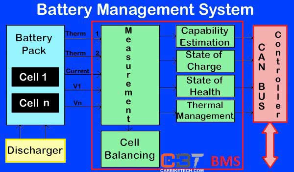
What is a Battery Management System or BMS?
BMS stands for Battery Management System. It is a type of electronic management system for newer generation EV batteries. BMS is just like the EMS in an internal combustion engine. So, it is a power electronics circuit board. In conclusion, it manages, controls & regulates the rechargeable battery cell or battery pack.
Purpose of BMS:
- Monitor the state of the battery
- Protect the battery from operating outside its safe operating zone
- Calculate report & the secondary data
- Controlling the battery environment
- Authenticate and/or balance the battery
Generally, a smart battery pack is built with a battery management system and an external communication data bus. Hence, to charge such a smart battery pack, you must use a smart battery charger.
The Functions of BMS:
- Monitor the voltage, temperature, coolant flow & current
- Energy recovery in EVs: BMS will also control the recharging of the battery. So, it redirects the recovered energy from regenerative braking back into the battery pack.
- Compute the values based on –
- Voltage, State of charge (SOC) or Depth of discharge (DOD),
- The State of health (SOH),
- State of power (SOP),
- State of Safety (SOS),
- Maximum charge current as a charge current limit (CCL),
- Maximum discharge current as a discharge current limit (DCL),
- Energy [kWh] delivered since last charge or charge cycle,
- Internal impedance of a cell (to determine open circuit voltage),
- Charge [Ah] delivered or stored (sometimes this feature is called Coulomb counter)
4. Total energy delivered since first use,
5. Total operating time since first use,
6. Total number of cycles
7. Communicates internally with its hardware operating at a cell level, or externally with high-level hardware.
8. Protects the battery by preventing it from operating outside its safe operating area.
9. Connects the Battery to the load circuit.
10. Balance the cells.
Battery Management System Topologies:
There are three main topologies of the Battery Management System.
- Centralized: A single controller connects to the battery cells through multiple wires
- Distributed: Each cell has a BMS board with just a single communication cable between the battery and a controller
- Modular: A few controllers, each handling a certain number of cells, with communication between the controllers
Main Categories of BMS:
1) PCM – Protection Board without Cell balancing
2) Hardware BMS (Regulation, Protection, and Cell balancing)
3) Smart BMS (Firmware based, Programable, Communication For Remote Monitoring, Control and Data Transfer)
Components of Battery Management System:
- Battery cells
- Electronic circuit board
- Controller
- Communication / data cables
- Set of wires
Centralized BMSs are the most economical. However, they are least expandable and have a multitude of wires & cables. On the other hand, distributed BMSs are the most expensive. But, they are simplest to install and have the cleanest assembly. Modular BMSs offer a combination of features and problems of the Centralized & Distributed BMSs.
Requirements of Battery Management System:
First of all, the requirements for a BMS in electric vehicles and any stand-alone UPSs are fairly different. They differ, especially from the space and weight limitations. So, the implementations of hardware and software must be custom-made for a specific purpose.
Furthermore, in the case of electric or hybrid vehicles, the BMS is only a sub-system. It cannot work as an independent device. Besides, it must communicate with at least a charger or charging set-up, load, thermal management, and emergency shutdown subsystems. Therefore, a good vehicle design closely integrates the BMS with these subsystems. Additionally, some applications such as scooters, motorized wheelchairs, medical equipment carts, and forklifts often have external charging hardware. However, the onboard BMS must also have close design integration with the external charger.
How & what does BMS Compute?
A BMS may calculate values based on the following factors, such as:
- Voltage: minimum and maximum cell voltage.
- State of charge (SOC) or depth of discharge (DOD) to indicate the charge level of the battery.
- State of health (SOH): It is a measurement of the remaining capacity of the battery as % of the original capacity.
- The State of power (SOP): The amount of power available for a defined time interval under the current power usage, temperature and other conditions.
- State of Safety (SOS).
- Energy [kWh] delivered since last charge or charge cycle.
- Internal impedance of a cell (to determine open circuit voltage).
- CCL: Maximum charge current as a Charge Current Limit.
- DCL: Maximum discharge current as a Discharge Current Limit.
- Charge [Ah] delivered or stored (Also known as Coulomb counter).
- Total number of cycles.
- The Total operating time since first use.
- Total energy delivered since first use.
So, various battery balancing methods are in use. However, some of them use the State-of-charge system.
How BMS works?
The central controller of a BMS internally establishes communication with its hardware operating at a cell level or externally with high-level hardware.
High-level external communications are simple and use the following methods:
- Different types of serial communications.
- Automotive environments commonly use CAN bus communications.
- Different types of Wireless communications.
Low voltage centralized BMSs mostly do not have any internal communications.
Furthermore, distributed or modular BMSs must use low-level internal cell-controller (Modular architecture) or controller-controller (Distributed architecture) communication. These types of communications are difficult, especially for high voltage systems. However, the main problem is the voltage shift between cells. For example, the first cell ground signal could be hundreds of volts higher than the other cells’ ground signal. Apart from software protocols, hardware communication uses two known ways for voltage shifting systems: Optical-isolator and wireless communication.
In addition, another limitation for internal communications is the maximum number of cells. For modular architecture, most hardware is limited to a maximum of 255 nodes. For high voltage systems, the seeking time of all cells is another restraint. It limits the minimum bus speeds and loses some hardware options. The cost of modular systems is vital because it may be comparable to the price of the cell. Combination of hardware and software limitations result in insufficient options for internal communication:
- Isolated serial communications
- Wireless serial communications
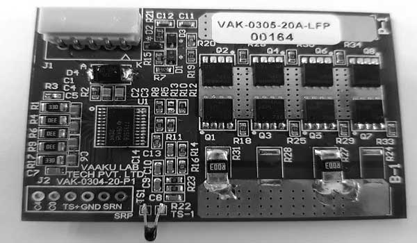
Bosch, Ion Energy, Eleo, Eberspächer Vecture, Vaakulab, and Jascon Energy are some of the Battery Management System manufacturers in the world.
Watch a Battery Management System in action here (Microchip):