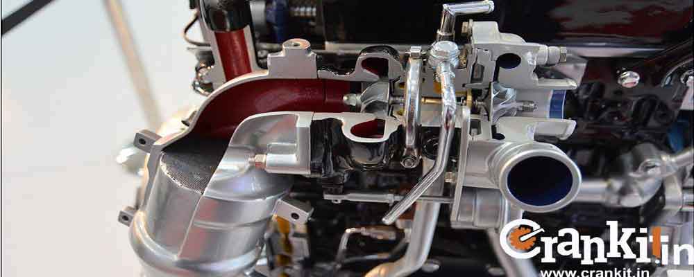
What is Variable Geometry Turbocharger or VGT?
Variable Geometry Turbocharger or VGT is a type of turbocharger. It is a mechanical device that increases the pressure of air by compressing it. Another name for the Variable-Geometry Turbocharger (VGT) is Variable Nozzle Turbines (VNT). VGT allows an effective aspect ratio (A:R) for the turbocharger according to varying conditions. Therefore, manufacturers usually design VGTs to deliver refined performance.
Manufacturers employ VGT because the optimum aspect ratio at low engine speeds is very different from that at high engine speeds. If the aspect ratio is too large, then the turbocharger will not be able to create the required boost at low speeds. Conversely, if the aspect ratio is too small, the turbocharger will fill the engine with more air at high speeds. Thus, it results in high exhaust manifold pressures and high pumping losses. And, ultimately, it lowers the effectual power output.
How Variable Geometry Turbocharger or VGT works?
The turbocharger can maintain the aspect ratio at its optimum levels by varying the turbine housing geometry as the engine accelerates. Because of this, VGT offers minimum lag. It has a low boost threshold and is very efficient at higher engine speeds. VGT does not need a waste-gate.
Applications of Variable Geometry Turbocharger:
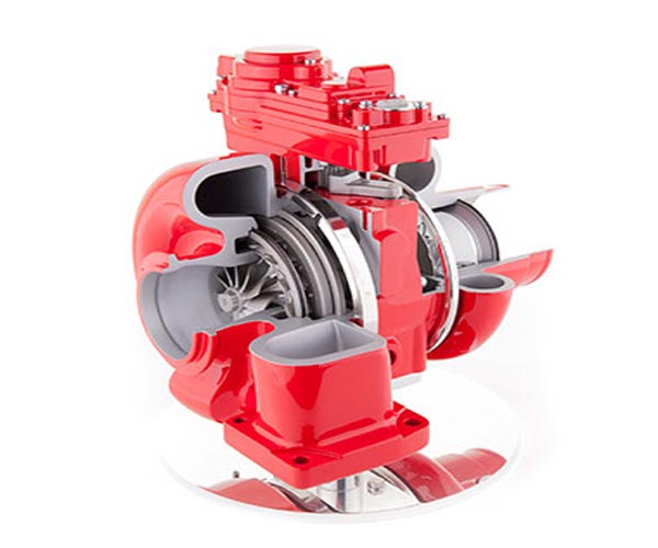
The two most common applications include a ring of aerodynamically-shaped vanes in the turbine housing at the inlet. Manufacturers use the first type in the passenger cars, race cars, and light commercial vehicles, which use light-duty engines. In this design, the vanes rotate in unison. As a result, they vary the swirl angle and the cross-sectional area of the turbine.
Manufacturers use the second type for heavy-duty engines, such as commercial vehicles. In this design, the vanes do not rotate. However, instead, an axially sliding wall mechanism selectively blocks the width of the turbo inlet. In this design, either this mechanism partially covers the vanes of a moving slotted shroud, or they somewhat move against a stationary slotted shroud. In addition, it varies the area between the tips of the vanes. Thus, it results in a variable aspect ratio.
Parallel Turbochargers:
Manufacturers use the term ‘Parallel Turbochargers’ when they employ two identical turbochargers in size and function. Generally, V engines employ Parallel turbochargers as one turbo serves each bank of cylinders. A ‘V’ engine has two separate exhaust manifolds with plumbing on both sides of the cylinder banks. Some manufacturers refer to this design on the V engine as bi-turbo.
Here, the advantage is the simplicity of its design. It is more challenging to connect two inlet manifolds to a single turbocharger and reduce the turbo-lag. It is because the two smaller turbochargers would spin faster than a single large one. Sometimes, manufacturers also employ Parallel turbochargers in the in-line engines, such as an inline-6. This design has little difficulty while reducing the turbo lag. It is because mounting two turbochargers on a single intake manifold is slightly more complex.
Sequential Turbocharger:
The second type is the Sequential Turbochargers, which are not identical in their function. However, they operate as primary and secondary turbochargers. Therefore, there are two sub-categories of the Sequential turbochargers. These are – (1) two turbos of identical size or (2) two turbos of different sizes, including a smaller-primary and a larger-secondary turbocharger. Sometimes, the manufacturers refer to the second type as ‘Variable Turbochargers.’
Generally, the design of the Sequential turbocharger is more complicated than the parallel turbocharger. It is because, usually, both turbos have separate plumbing to the same manifold/s. The Sequential turbo can also restrict the entry of the exhaust gasses into the secondary turbocharger or both of them.
How a Sequential Turbocharger works?
At low engine RPM and engine speeds, the Sequential turbo sends the compressed air only to the first/primary turbo, which doesn’t require much air for spinning. However, as the engine RPMs or speed increases, this turbo opens up a valve and allows the air to enter the secondary turbo. If both the turbos are of the same size, they provide a boost at high engine RPMs/speed. However, in sequential turbos, the mechanism can block the primary turbo. Thereby, it allows only the secondary turbo to provide the boost.
The sequential turbocharging provides a usable boost and a broader RPM range, especially at lower speeds. Generally, manufacturers employ the variable turbos on twin-turbo diesel engines. You can connect the plumbing after the turbos to a common intercooler. However, some advanced designs use two separate intercoolers, especially those with parallel-turbos, such as the BMW M5 engine.
What is Wastegate?
This feature of the Variable Geometry Turbocharger consists of a bypass valve built into the turbine housing. The waste-gate bypasses some part of the exhaust gases going through this valve to the turbine. It is as shown in the diagram.
The waste-gate arrangement reduces the high boost pressure created by the compressor and limits it to the desired value. Thus, it obtains the optimum engine performance with controlled peak cylinder pressure. As a result, Cummins and Holset are some of the world’s most popular manufacturers of Variable Geometry Turbochargers.
Watch Variable Geometry Turbocharger (VGT) in action here:
Read more: What is Variable Valve Timing?>>